
Cummins and Case “Locked Timed” application with the CDC Cummins engine
Removal
Clean the exterior of the injection pump and mounting surfaces.
IMPORTANT: Never steam clean or pour cold water on an Injection pump while the pump is running or while it is warm. To do so may cause seizure of the injection pump.
- Disconnect the fuel return line(s).
- Remove the injection pump supply line.
- Remove the high-pressure injection lines.
- Disconnect the electrical wire to the fuel shutoff solenoid valve, if equipped.
- Remove the fuel air control tube, if used.
- Disconnect all control linkage. Refer to the OEM service manual
- Remove the injection pump rear support bracket.
- Remove the access cap, gear retaining nut, and washer.

- Locate top dead center for cylinder Number 1 by barring the engine slowly, while pushing in on the top dead center pin.
NOTE: Be sure to disengage the pin after locating top dead center.
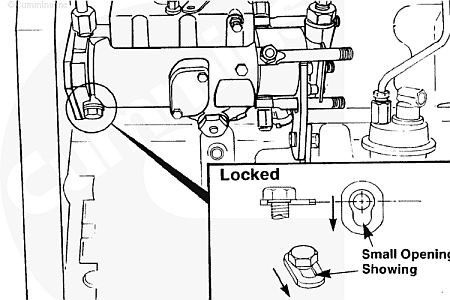
- The special locking plate on the Delphi injection pump must slide to one side so the lock screw can be tightened against the drive shaft. The smaller of the two openings will be showing and the lock plate will be loose against the screw.

- Pull the fuel injection pump drive gear loose from the pump drive shaft. Use fuel pump gear puller, remove the three mounting nuts and take off the fuel injection pump.

Important: Do not drop drive gear key when removing the pump. If the drive key falls into the engine it can result in severe engine damage.
NOTE: Injection pumps designed to meet Tier 2/Stage II Industrial emissions levels have straight holes (not kidney slots) and do not use a timing key.
Inspection
- Remove the gasket material and clean the surface making sure that it is smooth and free of burrs.
- Inspect the pump driveshaft for metal transfer from gear slippage.
- If the shaft shows signs of gear slippage, the injection pump is likely seized and the cause of the seizure must be determined before reinstalling the repaired or replacement pump. The drive gear must also be replaced.
Installation
- Verify cylinder Number 1 is at top dead center by barring the engine over slowly while pushing in on the top dead center pin.
- Install a new gasket on the injection pump
- The drive shaft must be clean and free of all oil before installation. Failure to make certain the drive shaft is free of oil can result in the drive gear slipping on the shaft (on pumps with no timing key).
NOTE: The shaft of a new or rebuilt pump is locked so the key aligns with the drive gear key way when cylinder Number 1 is at top dead center on the compression stroke. Install the pump. Make sure the key does not fall into the gear housing.
NOTE: Injection pumps on engines designed to meet Tier 2/Stage II Industrial emissions levels have straight holes (not kidney slots) and do not use a timing key.
- Hand-tighten the three mounting nuts, the pump must be free to move in the slots.
- Install the pump drive shaft nut and spring washer. The pump will rotate slightly because of gear helix and clearance. This is acceptable, provided the pump is free to move on the flange slots and the crankshaft does not move.
- Torque drive shaft nut to initial torque. Torque Value: 15 to 20 nm [132 to 177 in-lb]
- Take up gear lash by rotating the pump against the direction of drive rotation. Tighten the flange mounting nuts.
- Be sure the engine timing pin is disengaged before the final torque step to avoid damage to the timing pin.
- Loosen the fuel pump lock timing screw and slide the special washer to the side so that the large opening is showing, this allows the lock screw to be tightened against the lock plate and not the driveshaft.
- Tighten the fuel pump lock timing screw.
- Torque driveshaft nut to final torque specification (Lucas/ Delphi CAV/DPA pump 81 nm [60 ft-lb], see your service manual for other torque specifications.
- Install the injection pump support bracket.
- Install all high-pressure fuel lines and leave one line loose at the injector.
- Install the injection pump supply line, leave loose for bleeding.
- Connect the fuel return line, leave loose for bleeding.
- Connect the electrical wire to the fuel shutoff valve.
- If required, install the air-to fuel control valve.
- Connect all control linkage. Refer to OEM service manual.
NOTE: When connecting the cable and rod to the control lever, adjust the length so the lever has stop-to-stop movement. Adjust the cable or rod to the mechanical shutdown lever so there is stop-to-stop movement. Excessive travel will wear out the throttle and shutoff shafts sooner than normal.
Priming and Starting
- Install a new fuel filter and operate the hand primer on the supply pump, when fuel flows freely from the fuel inlet line tighten the fuel inlet line at the injection pump.
- Continue to operate the hand primer on the supply pump until fuel flows from the return line, tighten the return connection.
- Crank the engine until fuel flows from the one injection line, that was left loose, then tighten the injection line.
- You may need to bleed each injection line one at a time until fuel flows from each line.
- Start the engine and check for fuel leaks.